Sep 20, 2018
 ~4 minutes

Replacing the Amiga 1200 Capacitors
I’ve been upgrading and revamping my old Amiga 1200 a little recently. A while ago I replaced the ROM chips and installed a compact flash with Workbench and around that time also installed a Gotek drive. I’ve since made some modifications to the Gotek which I’ll show in a future post.
In this post I’ll give a bit of background to the process I went through replacing the capacitors. I got a kit from a UK eBay seller, and confirmed that all of the replacement capacitors were indeed genuine Panasonic before continuing.
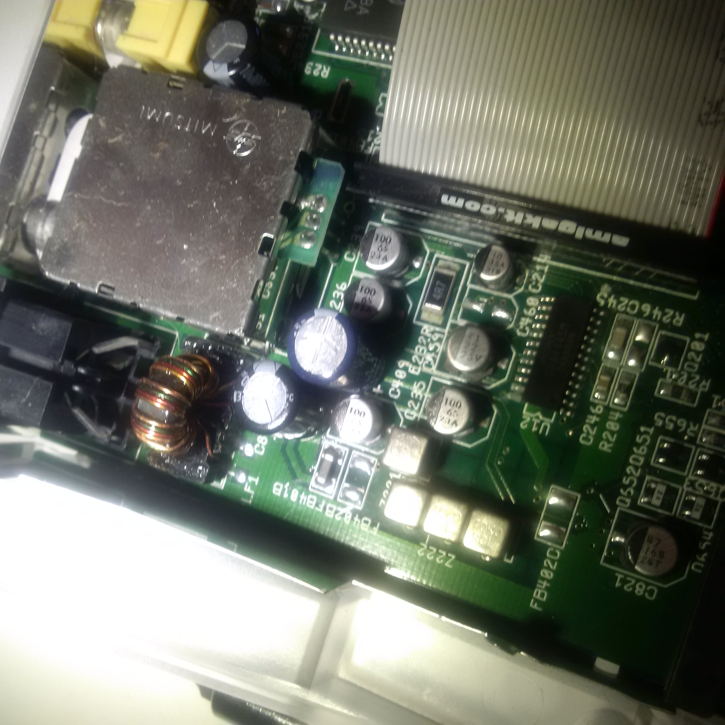
The capacitors to replace are all of the large cylindrical capacitors, as these are the components that are likely to fail, especially in 20+ year old technology such as the Amiga 1200. Most of the capacitors are surface mounted, although there are about 4 that are through hole. Prior to this I hadn’t attempted to (de)solder any surface mount parts, so it was quite an interesting, yet scary endeavour.
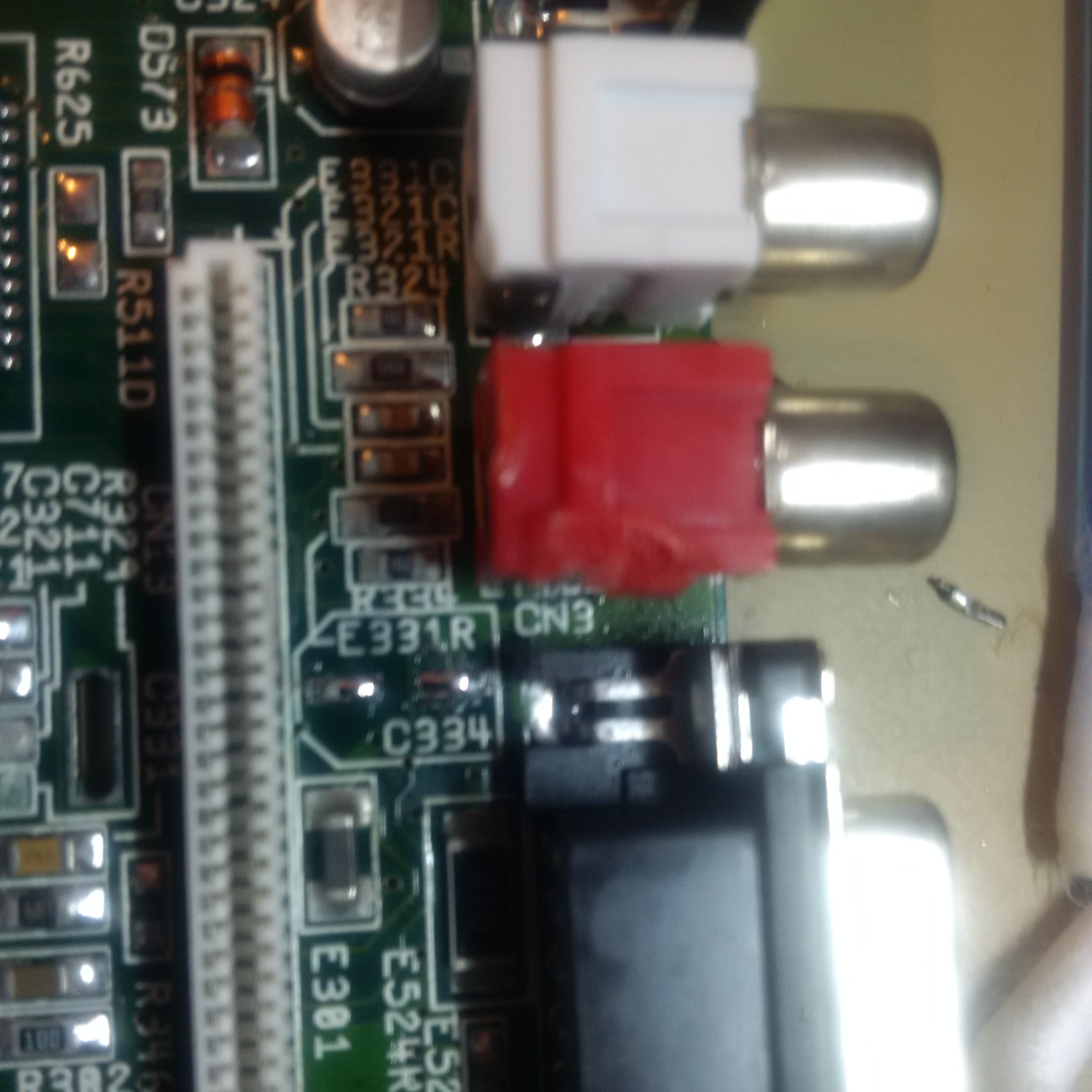
One of the first issues I found was the placement of a capacitor that’s awkwardly placed between the keyboard connector and the audio outputs. At first I attempted to remove the connector, and thought it wouldn’t be too hard. However, even with a new solder sucker, it proved problematic - probably in part due to the old solder, and perhaps the type of tip I was using on the iron - the heat didn’t seem to be penetrating enough particularly on the ground pins.
Part way through, I realised that I could remove the plastic retainer part of the connector which gave another mm or so clearance. I singed the audio connectors, but only superficially, but it worked fine.
Removing the SMD capacitors was also trickier than I expected. The caps have legs bent underneath, and if you attempt to tilt them sideways it becomes quite easy to damage the pads on the motherboard, which I did slightly with my first try. The next couple I removed by using a more brutal, but arguably effective, way by cutting the tops of the caps - there again is a need to be absolutely sure to cut in the same direction as the legs without applying any lift or tilt strain. This is fast and effective, but not recommended. The best method I ultimately found was to desolder the legs one at a time, holding one pad down while lifting the capacitor on that side. This results only in the other leg being bent backwards and doesn’t risk any strain to the pads.
Once removed, I used desoldering braid and isopropyl alcohol to clean the pads before adding fresh solder. Fitting the new caps is as easy as lightly holding them in place while touching edge of the solder until they sit in place. I did hear of someone pulling the legs out slightly before doing that, but I found that caused more problems than it solved.
With the SMD caps sorted, I worked on the through-hold capacitors. Again, I thought this was going to be easy - I’d worked with through-hole soldering quite a bit and was more confident. However, again the ground pins caused me problems and I needed to ramp up the temperature further than I was happy with, and it took ages as I ended up with solder stuck in the hole. I finally managed to remove the solder by holding the soldering iron on one side of the board, and on the other by using the solder sucker. A bit awkward, but finally it worked.
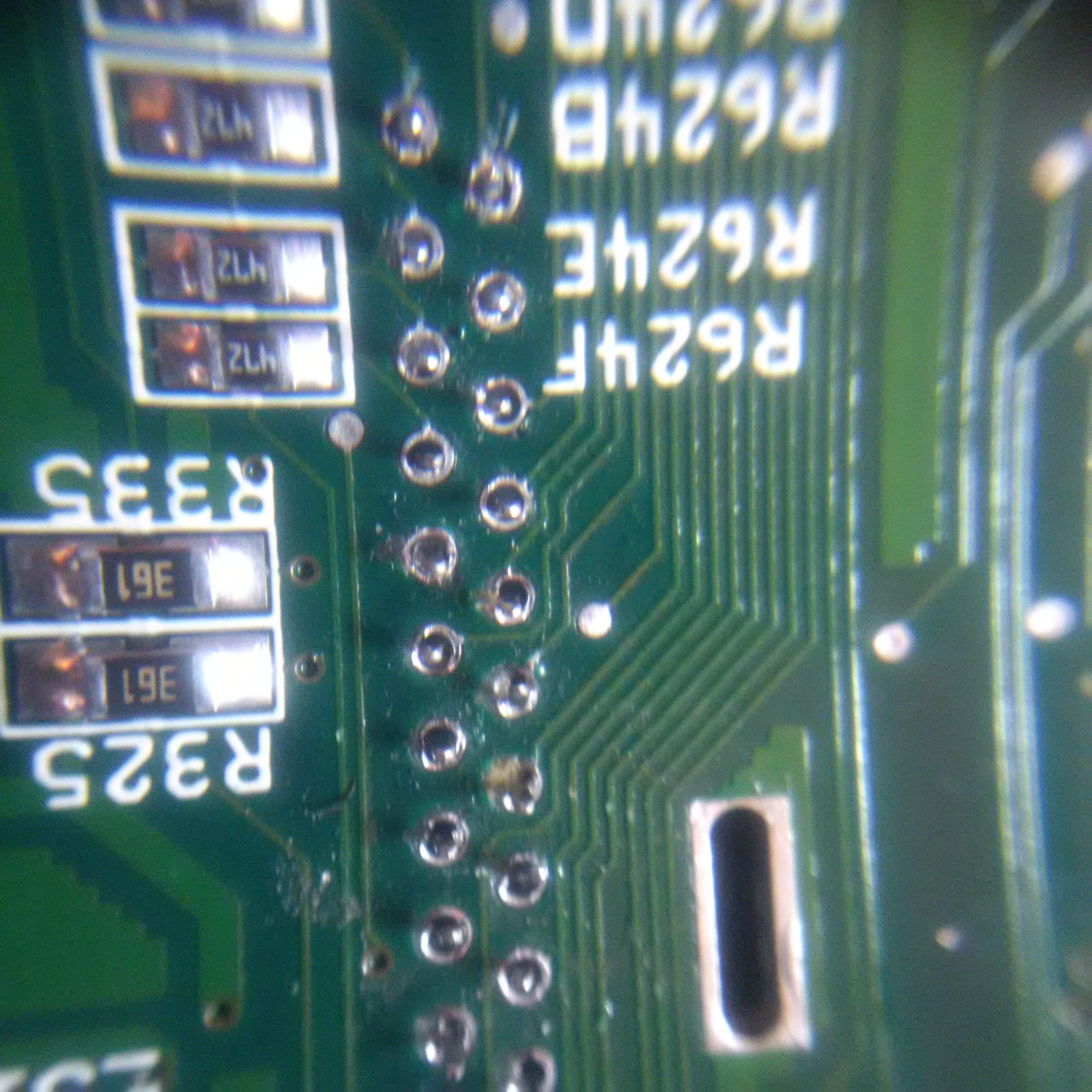
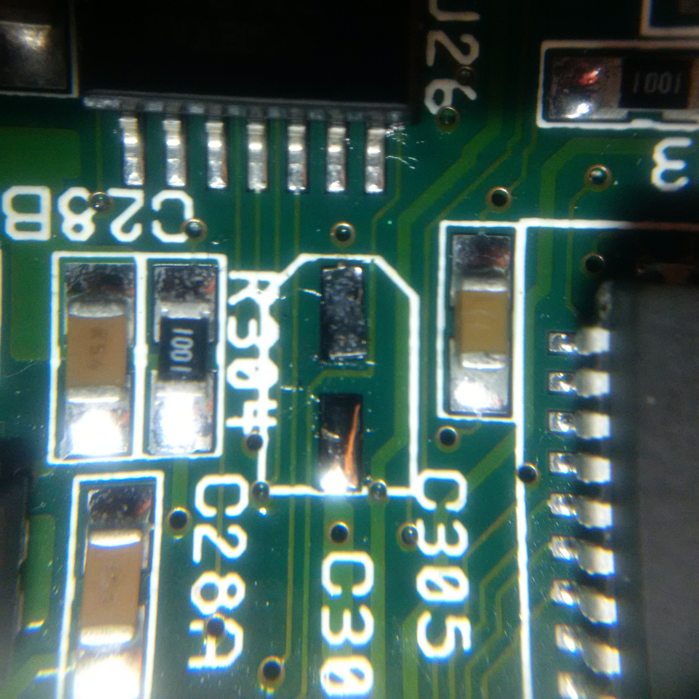
This is a picture of the worst pad, lifted slightly, although thankfully still intact and it resoldered just fine.
With all the capacitors replaced, I tried switching it on: good news was there was a green light and no ‘magic smoke’, bad news was there wasn’t any output. When looking for information I did find a really good guide to the boot sequence - there are some colours displayed when the Amiga boots to indicate hardware / software issues: https://amigalove.com/viewtopic.php?f=6&t=324
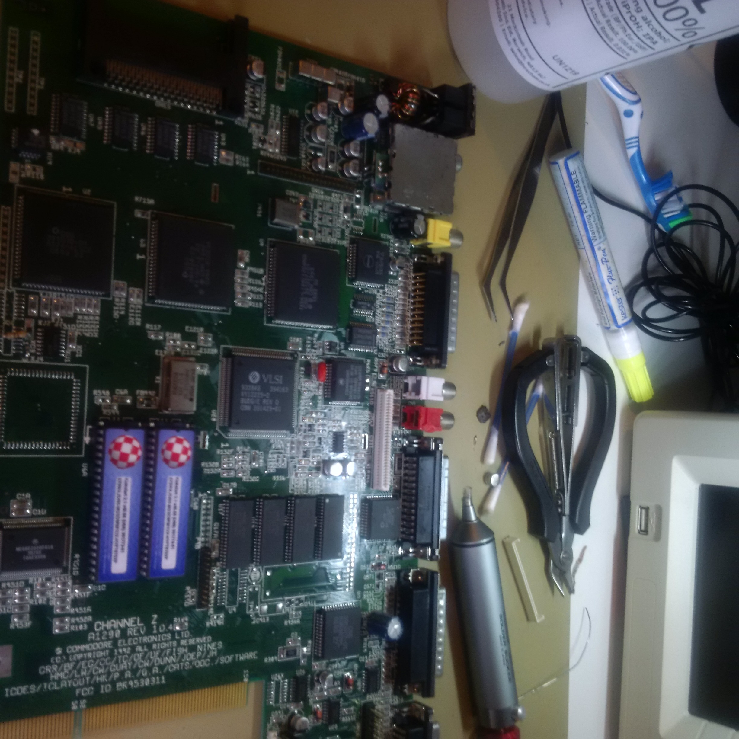
So, I again I stripped the A1200 down to the bare board, cleaned again with alcohol and ear buds, and scanned the board with a magnifying glass. There were a couple of tiny (fraction of a mm) fragments of solder, but none of them were anywhere that could have caused an issue… anyway, I plugged in the compact flash card, TV and tried switching it on, and it just worked! Putting everything back in place again, and it still worked.
Coming up in a future post will be upgrade of the Gotek to include an OLED display, speaker (to simulate the floppy sounds) and rotary encoder to make selecting disks so much easier.